 |
| The following document is a point-by-pont critical review of an article which I reviewed for Jack Cox some time in 1998. The article contain some basic truths. However, aside from my objections to a fear mongering and preachy writing style, many points in the piece argue with aviation wiring practices that have been in place for nearly 50 years. I also detect either disregard or lack of understanding as to the physics of joining conductors for a long service life. I suggested that the article not be published. Contrary to my recommendations, the piece appeared in the May 1999 issue of Sport Aviation. I was surprised and disappointed. Sport Aviation is the flagship publication of EAA. 135,000+ aviation enthusiasts look to this publication as the standard bearer of technical excellence. I've been putting off responding to this article. However, advice and words offered as fact have been quoted back to me on too many occasions. I am therefore driven to share my objections and observations of the work with the owner built and maintained aviation community. |
With all due respect to my friend, Bob Nuckolls, I must advise aircraft builders to follow only time tested and approved methods of attaching terminal lugs to wires for use in their homebuilt or even production airplanes. This article is based on nearly 20 years experience in our business of making extremely high quality power supplies, including transformers, inductors, DC and AC power sources for nearly all of the United States' and Japan's machine tool makers, servo and drive suppliers and OEMs of complex machinery. Our two plants make over 2,000 terminations a day and we have learned what works and what is approved (through experience) by the world's best electrical, electronic and machinery designers.
|
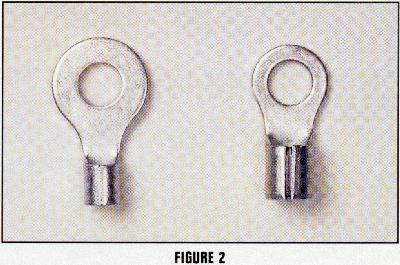
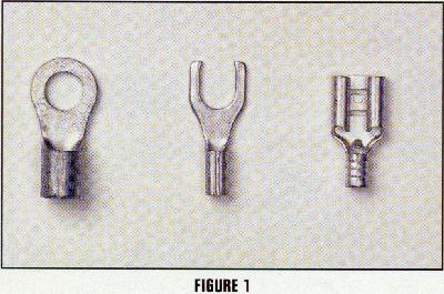
I'm unsure as to the significance of the terminals shown in Figures 1 and 2. One might infer that terminals in Figure 1 are not recommended while those in Figure 2 are. Figure 1 includes open spade and Fast-On terminals. In fact, the Fast-On terminal is an electrically and mechanically superior device as I've described in and article on my website which you may download by clicking here. I note that none of the terminals in the first two photos have insulators and insulation support.
For aircraft, auto and marine use, the closed ring lug is preferred since they are less likely to work loose from vibration and even if loose they may provide some connection until the screw holding them is completely vibrated out and gone (see rules to live by at the end of this article). Also (as Bob himself recommends) always use full closed ferrule lugs, never accept a split or open-ferrule (see Figure 2) for reasons that will be obvious when we get into crimping.
|
Insulated terminal lugs may seem like a time saving idea, even if they are about twice as expensive as plain lugs. This is a lousy way to save time. Insulated lugs cannot be soldered, they can only be crimped. Crimping isn't enough when your airborne beauty, and your body, are on the line! Should you try to solder an insulated lug, the plastic insulation will melt and leak all over the place, possibly even ruining the solder joint. Result in a bad job, extra cost and a mess all in one.
This statement argues with the talents and products produced by the likes of AMP (Now Tyco),Waldom, Holingsworth, and hundreds of other manufacturers who have worked diligently to produce a full line of solderless connection systems. It also argues with what has become standard practice in aircraft, automotive and power distribution disciplines for over 50 years.
I first put my hands on an AMP, Inc. terminal crimping tool at Boeing in the summer of 1961. The B-52 was reputed to carry over 500 miles of wire. 99% of my activities to put terminals or pins on wires used solderless crimp techniques. In fact, the use of a soldering iron anywhere near that airplane required the permission and inspection by my supervisor and the Boeing fire department. I used a soldering iron perhaps three times in 13 months. Each of those times I was told to have the proper signed-off solder-permission card in my possession before I plugged that critter in. Some B-52's are pushing 50 years old. If there are ANY original wires in these venerable old birds, my concerns would be NOT for the integrity of their CRIMPED terminals but for the INSULATION. That was the year 20 B.T. (before Tefzel) and the best that 3M and Monsanto could do for the world was PVC!
|
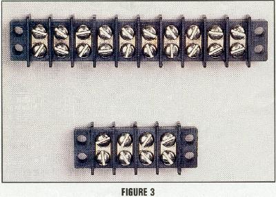
(1) the barrier strips illustrated use threaded, non-locking threads to maintain electrical integrity. When the use of such a device is necessary, the terminal strips of choice have threaded studs that are sturdy enough to accept self-locking nuts.
(2) Except for the connection of very fat wires to the threaded terminals of contactors, batteries, starters, and off-the-shelf products, we minimize the usage of threaded fasteners in electrical wiring wherever practical and possible.
I don't mean to imply that it's NEVER done but I've not had to use a threaded fastener terminal block for anything but BIG wires in a new design in over 25 years.
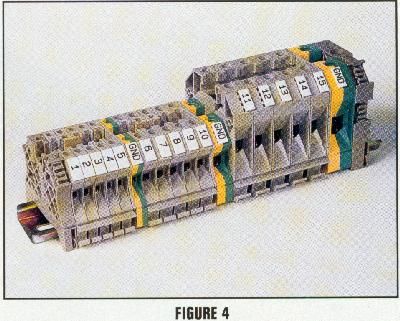
A variation in terminal blocks some constructors use is the increasingly popular international dead-front terminal blocks like those supplied by Phoenix, Entrelec, Altech, etc. (see Figure 4). They all mount on a standard "DIN" rail that can be grounded if needed. With these you merely insert a solder tinned wire end (no lug) into a hole in the block and tighten an internal screw for a positive permanent connection. Problem is they cost a lot more (about a buck per connection) and they take up a lot of space. Their advantage is ease of connection and the fact you can buy fuse blocks, breakers and a host of optional devices that snap on the same DIN rail. Never use "Wago" screwless terminal blocks; they cannot accept more than one wire per terminal and may allow wires to vibrate loose under extreme conditions.
|
Cinch blocks will neatly allow multiple connections, if needed, when ring lugs are used - a time and space saving advantage.
I am suspicious of phrases like "time saving advantage" . . . because they're often used without definitive comparisons with an alternative. If you design the requirement for a terminal strip out of the system, costs go down, parts count goes down, and numbers of joints in your wires goes down. Reliability goes up. I'll further suggest that you will save the MOST time by not using the device in the first place.
Rule I - Crimp to keep it from coming loose.
Rule II - Solder well for the juice.
Rule III - If in doubt, go back and repeat Rules I and II.
We will not allow a product to go out of our shop that does not conform to this standard - and we are the largest and fastest growing company in our industry. We will not accept field failures and there is no reason you should either!
These words pay homage to an old saw that has been hanging around for nearly a century, make your joint mechanically secure BEFORE you solder it for electrical security. I have books in my library that illustrate "proper" technique for joining wires used to carry power from pole to pole when the electrification of America was in it's infancy. Solder is not as strong as copper. Some technique that mates two wires so that the joint mechanically as strong as the original wire is called for. Obviously, you cannot simply twist wires together and expect continued electrical integrity . . . bare copper exposed to the weather WILL corrode and degrade the electrical integrity of the joint. Solder ENCAPSULATES the interface of the joint and preserves electrical integrity.
Over the years, elements of this description for "proper" joining of wires have found their way into other disciplines and planted erroneous notions about the properties of copper and solder. The idea that the copper "made it strong" and the solder "makes it connect" is incorrect. I will illustrate in more detail later. . .
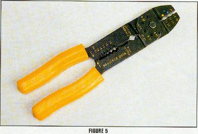
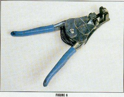
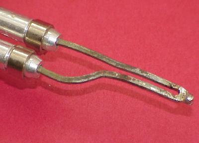
There are several ways to obtain a successful crimp on your lugs. The best way is to use a professional quality crimping tool (about $35 to $50 at your electrical jobber) with jaws sized for the lugs you are using. Good tools come with a variety of jaw sizes that are easily inserted in the tool. Alternatively, if you only have a few dozen to a few hundred lugs to attach, you may use an electricians pliers ($12 or so) that has typically three tooth sizes and also several wire stripping points (see Figure 5). That's what I use at home, on car projects and on my own homebuilt restoration project.
|
Given the low cost of these tools, there is really no reason for not taking advantage of the convenience and repeatability of results for putting INSULATED terminals on your project's wires.
|
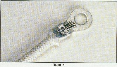
There's a difference between a good crimp and a bad crimp. A good crimp will produce a positive detent in the ferrule of the lug (see Figure 7). A good crimp will physically hold the lug on the wire beyond the breaking strength of either the lug or the wire. Test the crimp by pulling on the lug. If the crimp isn't enough and the lug pulls off, throw it away and use a new one. Lean on the crimp tool; unless you have a $100 reflex jawed production tool, you cannot break the lug. Lugs are made to be crushed into and deformed at the point of detent into the wire.
This paragraph argues with the published literature from folks like AMP and Waldom. Click here to download an article from my website that speaks to the anatomy of a good terminal. Information used to support this piece came right from the engineerng literature of the folks who manufacture solderless terminals.
|
Terminals are NOT tin plated for solderabilty, plating IS for corrosion protection. Two perfectly clean copper wires simply twisted together will conduct electrons from one wire to the other about as well as they ever could. However, exposure to oxygen, ozone, moisture, nitrous-oxides, etc will quickly corrode the shiny copper surface and make the joint something less than optimum.
Once the degradation starts, it is precipitous. As the joint's resistance goes up, heating due to voltage drop increases. Heating increases rate of corrosion which drives resistance up still faster. After a time, the joint fails electrically even if it's secure mechanically.
The trick of securing a long lasting joint is to keep the adverse effects of the environment away from the area where the two conductors are joined. This can be done several ways but by far the most popular are crimping -OR- soldering. Either technique properly utilized will do the job. It is not necessary to do both. It's interesting to note that the terminal in Figure 7 is installed on 7-strand wire insulated with a braided overjacket. NOT aircraft wire.
Most aircraft electrical wiring uses either AWG (American Wire Gauge) 14, AWG 18 or AWG 20. A box of lugs for each will cost only a few dollars per size. Larger wires, such as starter connections, etc., may use AWG 8 for which properly sized lugs are 15-20 cents each. Extra crimping will not correct a wrong sized lug. Beware, lugs also come in a wide variety of screw sizes - do not oversize the screw hole or you will have a bad connection.
Slide the lug on the stripped wire allowing no loose or split strands. A wire strand that is outside the lug does no good at all. Experienced folks give the wire a slight twist to ensure the strands are compacted and slide easily into the lug. This also makes for a better crimp inside the lug because the deformation encounters a twisted group of strands rather than merely crushing the top ones against the bottom ones. We will not ship a product that has a single split strand! You better not either.
The writer simply doesn't understand how crimping works. If you cross section the
squashed area where a terminal's wire grip is formed over the strands of wire, the optimum crimp totally squeezes out all open volume within the joint. The ideal joint is said to be "gas tight" meaning that not a
single molecule of air (or moisture) can find its way into the joint. For all practical purposes, the terminal and wire have become a single entity.
Once the ideal crimp is achieved, nothing you can add in the way of solder is going to improve upon the joint either mechanically or electrically. The notion that twisting the strands before inserting them into the terminal's wire grip is intuitively flawed. If the goal is to form the terminal and wire stranding into a homogenous mass of tin-plated copper, how does this goal benefit by causing the strands to lay in anything but neat, parallel bundles to await the supper-squash of your crimping tool? Interestingly enough, the wire manufacturer's goals are similar. If the strands of wire are not disturbed as you strip of the insulation, you find that the strands are tightly stacked with a minimum of gap between the strands. These strands are ready to go into the terminal for crimping with no further attention.
These words echo admonitions cited earlier from very old books on wiring. The "make it strong" then "make it connect". These words foster a belief that solder should not be depended upon as a structural material. I went to my workbench and pulled a 0.032" diameter strand of 63/37 solder apart while reading the force on a spring scale. The average of 4 experiments yielded a tensile strength of 63/37 alloy solder as something on the order of 3200 pounds per square inch. It's probably better than that because the solder I measured was hollow so that it could contain flux. But for now, let us use 3000 psi. Obviously, solder is not for fabricating wing spars but let's consider the joining of wires.
Raychem makes a device called a "Solder Sleeve" that is designed to
join two wires by simply overlapping the stripped ends about 1/4"
and shrinking the sleeve down over the joint.
Here is an exemplar spec sheet on
Tyco/Raychem Solder Sleeves. Rings of sealant
in each end of the sleeve close off the joint for environmental protection
while a ring of solder joins the two wires. All in one single operation with a heat gun.
Let's assume the sheer strength of solder is only 2/3 its tensile strength.
Let us further assume two 22AWG wires stuck together with a cross-section of
solder approximately equal to the diameter of the wires times the length of
the joint (0.025 x 0.25 ) or 0.0063 square-inches. Multiply by 2000 pounds
and we get 12.6 pounds. Okay, back to the workbench. I stripped two wires
1/4" and lap soldered them together using a minimum of solder. I pulled on
this joint with my spring scale and maxed it out at 25 pounds without opening
the joint! A reasonable pull test of a crimped terminal on a 22AWG wire is
20-25 pounds.
Hmmm . . . if solder ONLY good for electrical connections and not to be relied
on as a structural element of wire joining, somebody better tell RayChem about this.
They sell solder sleeves by the bizillions. However, I'll suggest my simple
experiment shows that RayChem is not perpetrating a great evil upon un-suspecting
users of their products! In fact, if you like the solder sleeve concept for
wire joining and don't want to pay the freight for low quantity purchases of these
parts, check out this article I did on
"Poor Man's Solder Sleeves".
Let us consider that most modern electronics are now put together with surface mount components where solder is both the mounting and connection medium for all of the components on the board. Some of the components like transformers can be quite hefty. Consider also that houses plumbed with copper pipe have joints that are totally dependent on the structural integrity of solder. Let's dispel the notion that solder is some weakly substance akin to peanut butter to be used only as a concession for electrical integrity. This is simply not so. Solder is a material with useful thermal, chemical and structural properties. If used within easily deduced limits, solder as -EITHER- an assembly medium -OR- environmental shield can be quite useful.
Good quality rosin core electrical solder (generally 60/40) comes in a variety of sizes. We use fine wire solder for even the largest connections. This would be about the size of a heavy pencil lead. Only rosin core solder is allowed for electrical connections, because acid core solder (available in hardware stores for hobbyists, decorative and similar applications) eats away at the plating on your wire and eventually the wire itself. Failure will result(not may, will result) from the use of poor quality and/or acid core solder. We buy ours from Handy and Harman, but Kester and Canfield are good brands. Penny wise, pound foolish - expect to spend $15-$20 per pound for good electrical grade solder. Skimp here and you'll swear later because el cheapo solder can have other alloy metals than pure tin and lead causing high melting point, poor wetting and flowability.
The rosin core is a flux which chemically cleans the surface of the metal and is pushed away as the molten solder bonds to the plated surfaces of your wire and your lug. A little burned rosin (the characteristic smell of a good hot solder joint) around the edges does no harm. It is benign.
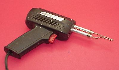
Never, ever use a torch on wire connections. A torch will burn insulation, it may melt off wire strands, it will heat from the outside not the inside and a whole bunch of bad things. The soldering gun is the best tool for fine electrical connections.
|
For very large wire sizes we use a solder pot. Several brands of soldering gun come with a variety of tip sizes to suit various wire/lug size combinations. Simply select the tip that heats your set-up quickly and cleanly. For production we use temperature controlled soldering irons that are on all day long, but our operators may make a hundred or more connections a day. The advantage of a gun is that it cools off almost instantly, minimizing the potential for damage should you put it down in the wrong place. This could be important when working inside your beauty. Further, a gun will not harm the insulation or anything else not actually touching the tip itself.
|
|
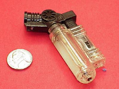
Nowadays, an extension cord is not needed to fire up my portable butane fired soldering iron. 99% of my soldering is accomplished with temperature controlled irons at my workbench. About 1% of my soldering is done in the field. Just this morning I pulled the butane fired iron out of my briefcase toolbox to fix a fussy controller board on a Premier I bizjet. I was done with the job in less time than it took the mechanics to get less handy tools from the crib.
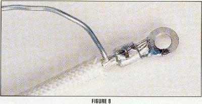
Soldering is an art that is easily mastered. The point of the gun (or iron) the tip should be rested firmly on the lug where it will touch the exposed wire end and heat the joint from the inside (see Figure 8). As the assembly heats up, poke the end of your rosin core solder at the backside of the lug where the wire extends into the insulation. When the joint is hot enough the solder will quickly melt and flow toward the heat source. "Solder follows the heat" is the rule. Feed enough solder into the back and then the front of the joint to fill the ferrule and make a smooth filled look at the ring end of the lug. Swiftly remove the gun and the solder and allow the joint to cool with no motion or disturbance. If it moves do it over again for you may have a "cold solder joint" which means the solder crystallized before adhering to the base materials. A cold solder joint will fail in service sometime in the future. A cold solder joint is dull in appearance. A good joint will be shiny and smooth. Accept nothing less.
|
The joints that work the hardest are the big ones where high amperage surges take place like where your starter, alternator and relays do their work. Take your time to make them right or make them over until they are right.
I've NEVER found it necessary to use a solder pot. To me, dipping parts to be assembled in a pool of molten solder is akin to painting your airplane by dipping it into a swimming pool full of paint. The solder pot has some useful applications but they get solder EVERYWHERE on the finished parts. Less expensive tools and a little skill are a very satisfactory alternative to solder pot joining of terminals onto wires. Click here to download an article I wrote some years ago illustrating a technique for assembling fat terminals on fat wires with
Before I turned my parts business over to B&C, I soldered ALL of my ground and battery jumpers with a small butane fired torch. Later on, I built an adapter to plumb the miniature torch burner to a propane bottle by way of a length of hose. A job did not have to be interrupted to refill the torch's tiny tank. A properly sized torch and a little practice are powerful tools for dealing with big wires in your airplane.
|
|
THE TERMINAL ADVANTAGE
Rules To Live By
Remember the phrase gas-tight? The area immediately adjacent to BOTH soldered and crimped joints is for all practical purposes, a solid wire. This is why the recommended terminals for smaller wires (24AWG to 10AWG) have TWO crimps that grip the wire. #1 crimp is an electrical connection in the wire grip barrel. #2 crimp is a metalic INSULATION grip that supports the wire immediately adjacent to the electrical joint so that bending moments at the joint are minimized. The heat shrink tubing recommended in this article would not be considered sufficient to this task. This is why AMP's pre-insulated, diamond grip (PIDG) terminals have METALIC liners inside the insulation sleeve to provide superior mechanical support. A terminal with plastic insulation cannot also be soldered without melting the plastic . . . Sooooooo . . . the best thing to to is install it with the proper tool and DON'T solder it.
| Mr. Burgher's credentials are impressive. Further, I am pleased for him and his employees if his customers perceive his products to be a good value. Credentials and customer perceptions aside, it's difficult to ignore variances between what he suggests in this article and what has become accepted practices by the aviation community and its most able suppliers. This article opens with the words, "I must advise aircraft builders to follow only time tested and approved methods of attaching terminal lugs to wires for use in their homebuilt or even production airplanes." I object to the word "approved" because fabrication of a system based on good physics and understanding requires nobody's approval. I further object to any implication that these "time-tested" techniques are embraced by anyone but the author. I too have a credential that now spans 40 years in aviation experience and my teachers have taught me differently. Instead of holding forth with "do this because I tell you it's the only right way", my teachers expected me to understand how things worked and why things failed. It's my sincere hope that I've been able to share some of that understanding with you. "Rules" are edicts from people having the power to punish you for failure to comply. I would prefer to offer my own list of talking points in the interest of fostering good art and science of designing, fabricating, maintaining and flying the world's finest aircraft:
'lectric Bob |