|
|
Bob's Shop Notes: |
|
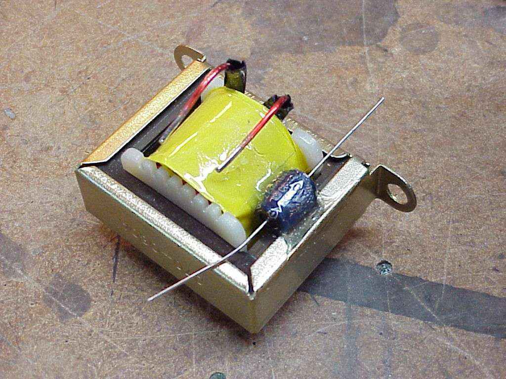
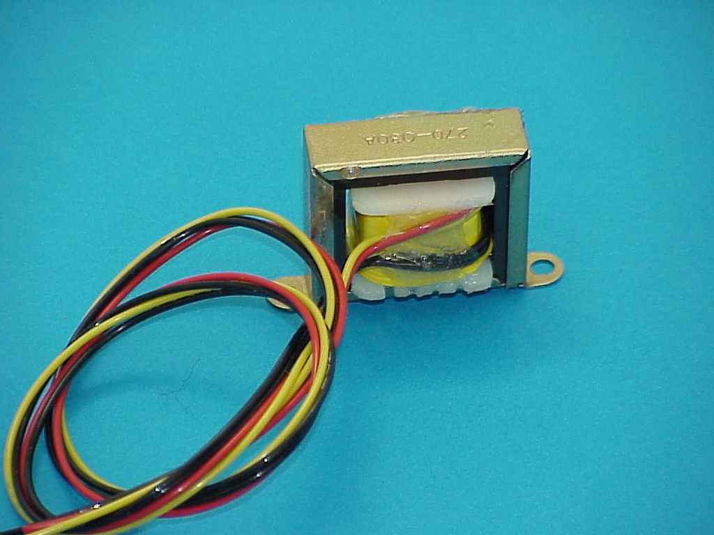
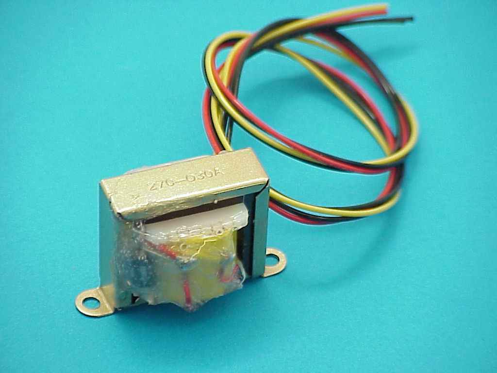
Tools needed: (1) A soldering iron with a 1/16" or smaller tip . . . wattage not terribly critical but it needs to be hot enough to melt the tip of a strand of solder in one second or so. 40W is certainly enough, many 25W irons will do. We're looking for a 650+ degree iron. (2) Wire cutters and strippers. Materials needed: (1) 63/37 alloy (or 60/40 alloy) solder. I like Kester Resin 44 but there are several good ones. (2) Tube of ShooGoo athletic shoe repair cement. Also sold in many hardware, automotive and hardware stores as E6000 industrial adhesive. (3) Noise filter kit #270-030 from radio shack. The kit will contain an iron core filter choke and an electrolytic capacitor. (4) Lengths of 20AWG Tefzel wire. I used red, yellow and black wires but any other colors can be used as can ordinary white wire . . . the colors just make it a bit easier to avoid wiring errors later. Make your leadwires long enough to facilitate final installation in the airplane with no splices. Step 1 . . . |
Step 2 . . .
|
|
|
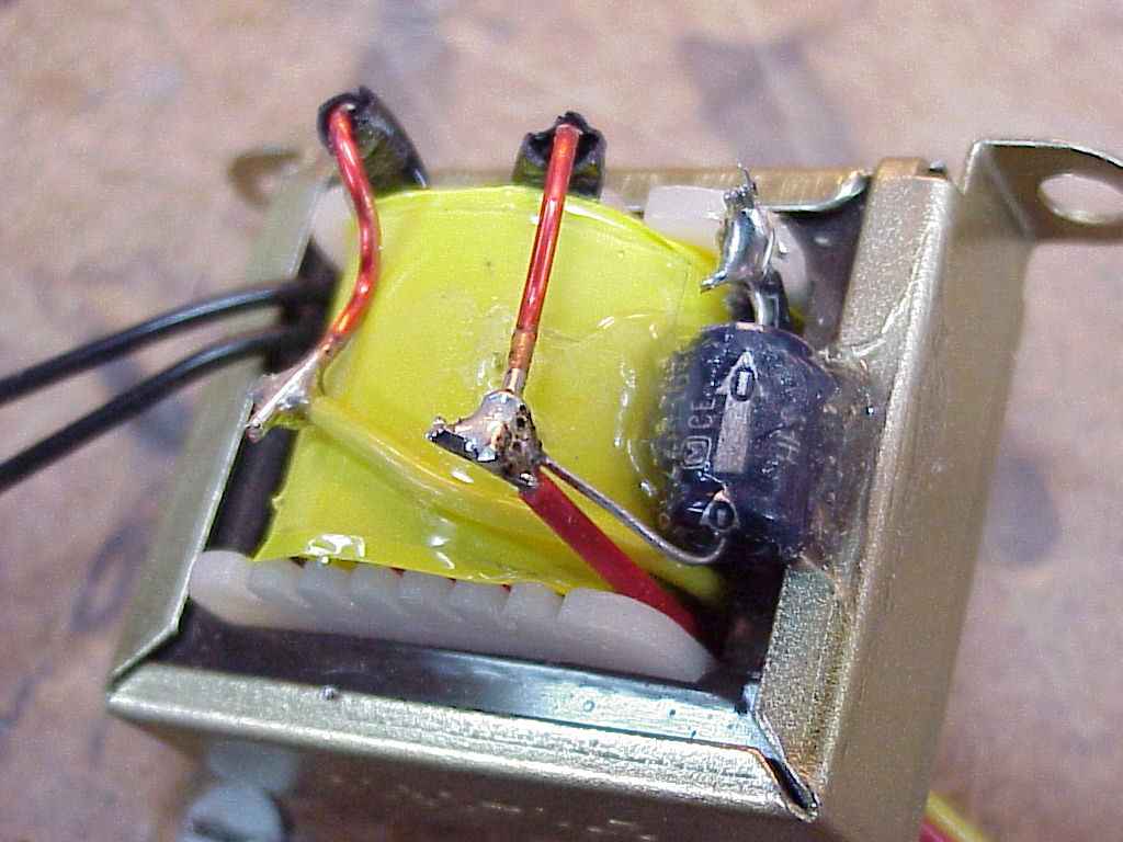
Step 3 . . .
|
Step 4 . . . |
|
|
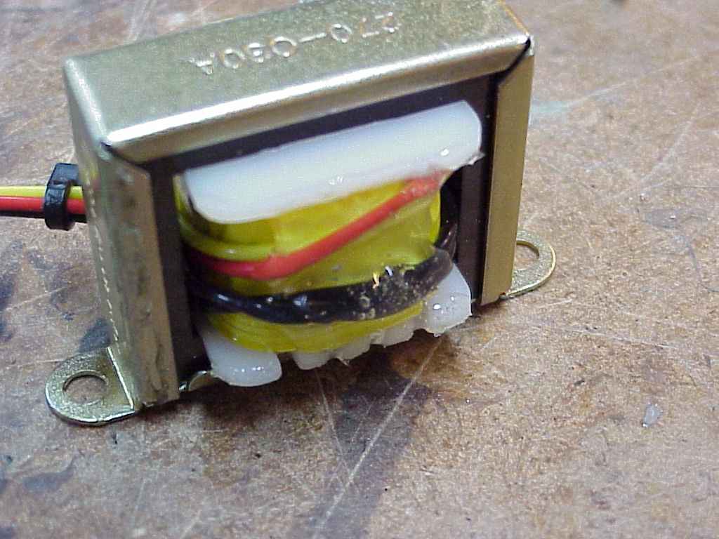
Step 5 . . .
|
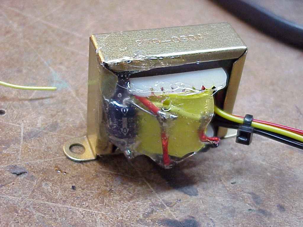
Step 6 . . .Use of the adhesive allows you to assemble these parts in a rugged, compact assembly with no additional connectors or metal work. Using the adhesive makes it a two day project but fortunately, total labor to assemble this filter is less than 30 minutes. To mount these components in any kind of enclosure adds bulk, weight, labor and possibly additional connectors. The adhesive is tough and stable . . . in this application, the filter may be mounted anywhere on the aircraft except under the cowl.
|
|
 Click here to contact Bob at AeroElectric Connection Click here to contact Bob at AeroElectric Connection |