![]()
|
Bob's Shop Notes: |
This Shop Note was first published about summer of 2003 in response to several reader reports of difficulty with RG-58 coax cable. This article suggests that the RG-58 can be replaced with a modern, high temperature shielded wire. I wrote the article at the suggestion of several builders who had already made the substitution and reported no problems with system performance. A few months after it was published, I received a fax from Lightspeed wherein Klaus was upset about the article. Seems a builder reported not being able to get sparks to jump between coil towers as called out in the post-installation acceptance testing. After replacing the shielded wire with coax, the ability to get sparks to jump the gap was restored. Klaus dressed me up one side and down the other about suggesting modifications to his product without consulting him first. Seems his engineer has concerns about capacity characteristics of coax versus shielded wire. Coax has slightly fewer PICOfarads per foot than does shielded wire. He also cited some voltage concerns. I'll have to confess to a certain degree of arrogance for not consulting him first . . . but then, the simple-ideas surrounding the substitution didn't seem to support much concern. Yes, there is a pretty good voltage transient on this wire . . . but most shielded wire of this genre' is rated at 600v with a breakdown voltage in the kilovolt range. Yes, the shielded wire has a higher capacity but we're taking PICOfarads. If the system operated with time critical signals measured in nanoseconds, we might begin to have some concerns about feedline capacity . . . but this simply isn't the case. I'm mystified by the test procedure requiring that sparks jump a 1.5" gap between coil towers . . . Klaus was fond of demonstrating killer sparks. His Multi Spark Discharge (MSD) system demonstrator was awesome to behold in the booth at OSH back in 1986. In may well be that this extra-ordinary performance truly helped win races. But I keep going back to the product mission for the masses. 99.9% of you don't race your airplanes. You want to use automotive plugs and get SLIGHTLY better performance from your engine. I'm skeptical that a spark that jumps only an inch between towers is critically different that one that jumps 1.5 inches . . . the gap in the plugs is only 0.060" or so . . . yes, it's under pressure, but still . . . In the final analysis, I cannot claim credit for the original suggestion . . . several readers had already done it and found no problems with it. Many more have done it since and report no problems. Further, they found the shielded wire much easier to work with. All I did was put some hammer-n-tongs suggestions to their repeatable experiments that demonstrated a valid substitution. In spite of Klaus' protestation I can find no compelling science to support the notion that coax cable is much superior to shielded wire in this application. However, there ARE modern, high temperature coax cables like RG-400 that can be used . . . and I believe Klaus is now recommending this material instead of RG-58. It's a step in the right direction but RG-400 is no easier to work with than RG-58 in terms of installation. I just received an e-mail from another builder reporting problems with RG-58: Bob, A while back your site had a download for an alternate to the Lightspeed RG58 to coil connection. I have a Lightspeed installed per instructions (RG58) and today found the center conductor insulation near the coil completely melted away. At 65 hours I was surprised, but I knew what I was looking at (thank you for that). I can understand the possible reasons for removing this download from your web site. If you can, would you tell me if you think your method was a bad idea, or was it removed for other reasons? This letter has prompted me to re-post the original article along with this narrative on circumstances surrounding the original posting and subsequent kerfuffle. I'll leave it up to builders to choose between (1) RG-400 coax cable which is made from much more robust materials than RG-58 and (2) Tefzel insulated shielded wire which has been successfully utilized in dozens of Lightspeed installations. As always, I'd appreciate any feedback readers can offer in their first-hand experiences and observations in this matter. The best decisions and designs are made on good data. Bob . . .
|
|
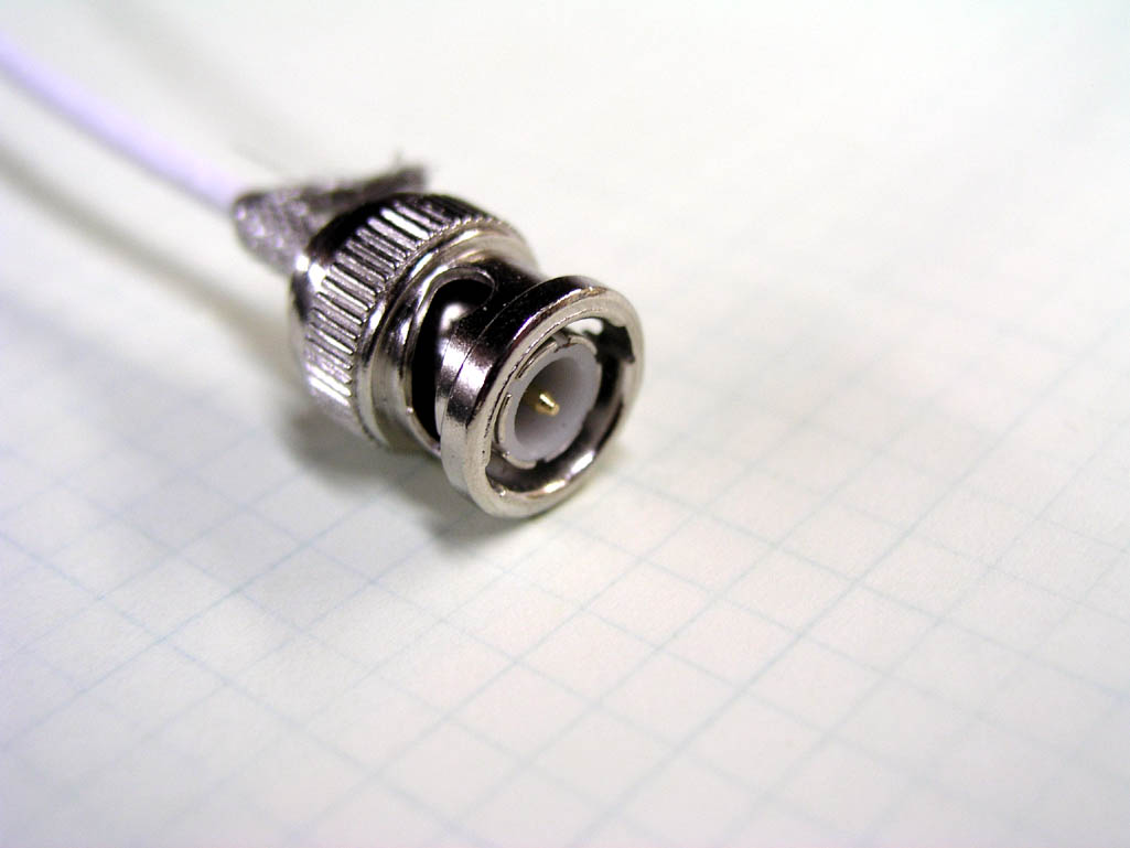
Instructions for the popular and capable electronic ignition system from Lightspeed recommends
RG58 coaxial cable for wiring between the ignition control module and high tension
coils on the engine. In this writer's opinion, it's difficult to pick a wire less
suited to this task. I base this opinion upon the types of materials
used for this venerable coax. RG58 has been around for nearly 60 years. It was a popular coaxial cable in World-War II era aircraft. The insulation materials were the best we had available at the time: polyvinylchloride (PVC) and polyethylene. Originally designed for use in relatively low temperature areas, this wire was widely specified into antenna feedline systems for airborne and ground communications. Six decades later, our operating frequencies of interest have gone up by at least ten-fold. Modern insulations with names like teflon, tefzel, kevlar, and kapton have been offered as having superior characteristics at radio frequencies and much more robust characteristics with respect to abrasion and environmental temperature. I'm not privy to details of why this now obsolete cable is recommended for the ignition system wiring. I suspect it was to take advantage of the very neat, low cost, easy to apply, bayonet locking BNC connectors designed for coaxial cable termination. While RG58 mates up nicely with BNC style connectors, use in the engine compartment is not recommended. Both insulations used in fabricating RG58 are particularly susceptible to ozone and heat induced deterioration. This wire was never intended for use in proximity of engines. A more modern coax like RG-400 could be considered but allow me to suggest an low cost, very robust alternative to coaxial transmission line in this application.
|
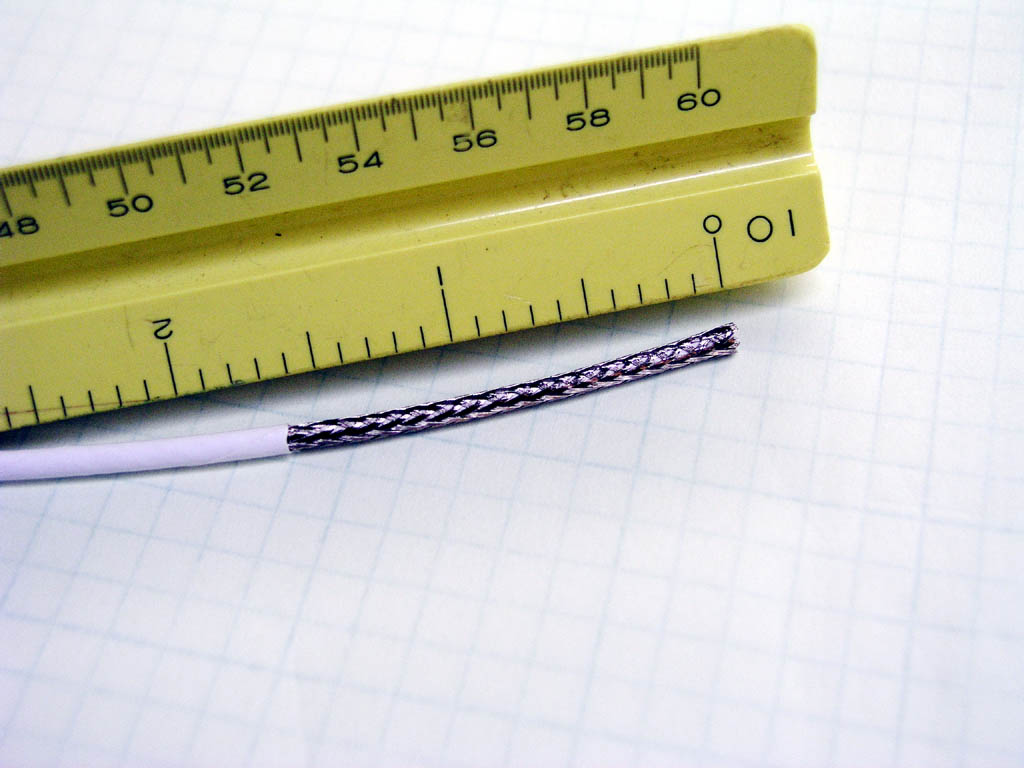
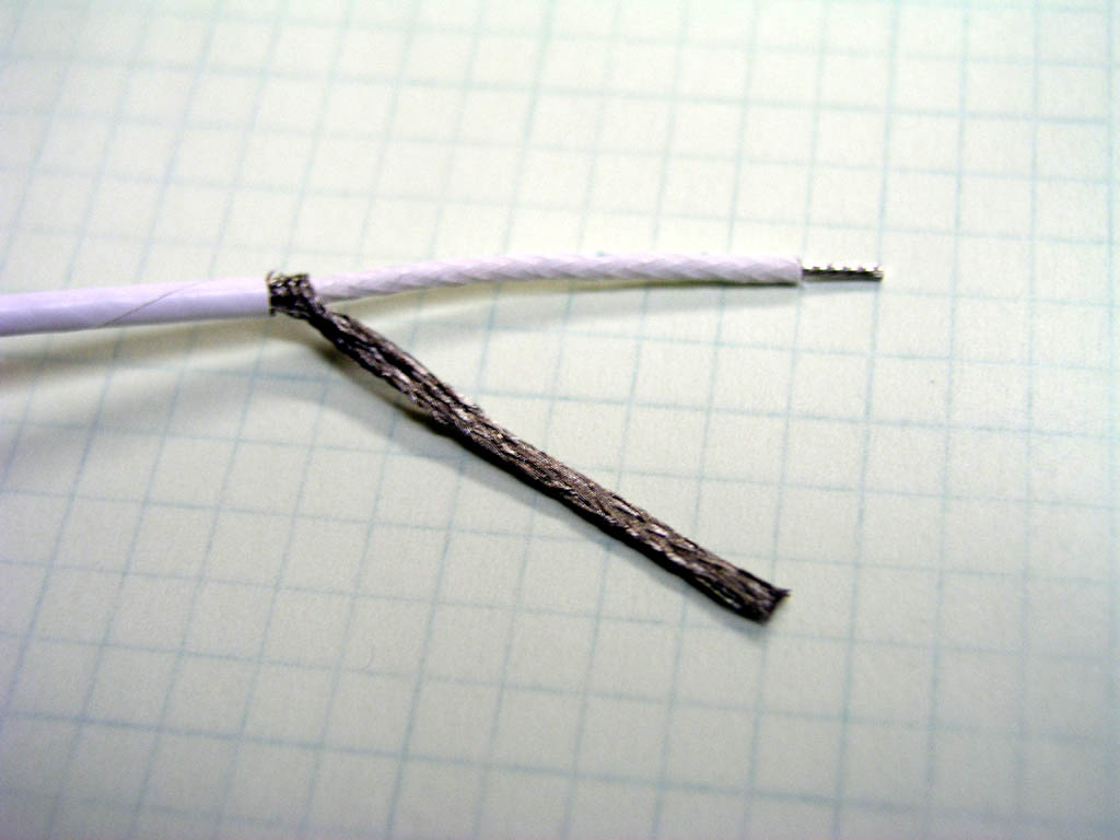
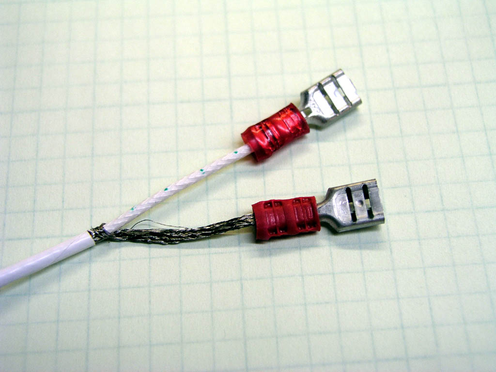
Step 1Start by stripping back about 1.5" of outer insulation |
|
|
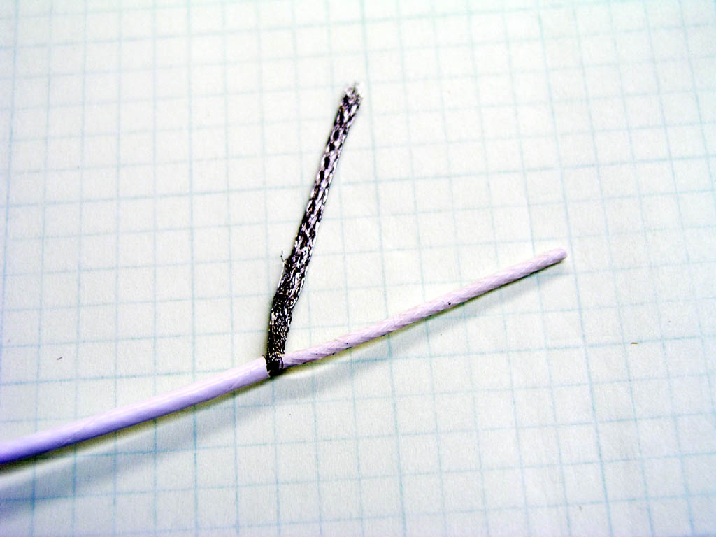
Step 2
|
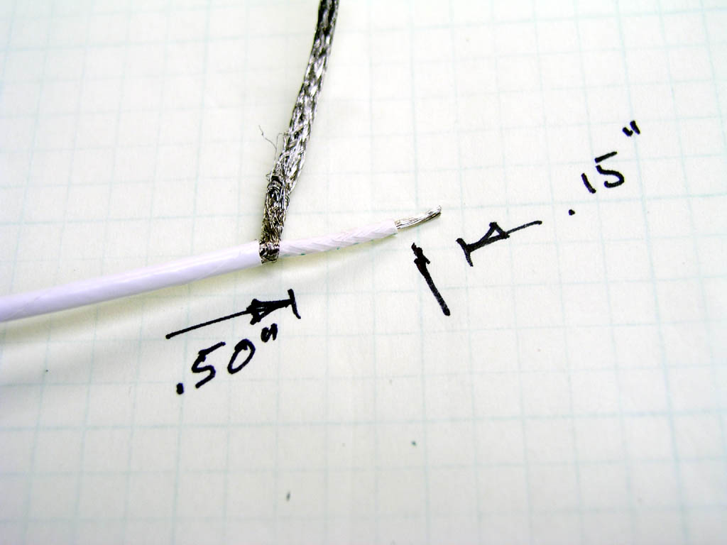
Step 3 |
|
|
Step 4 |
Step 5 |
|
|
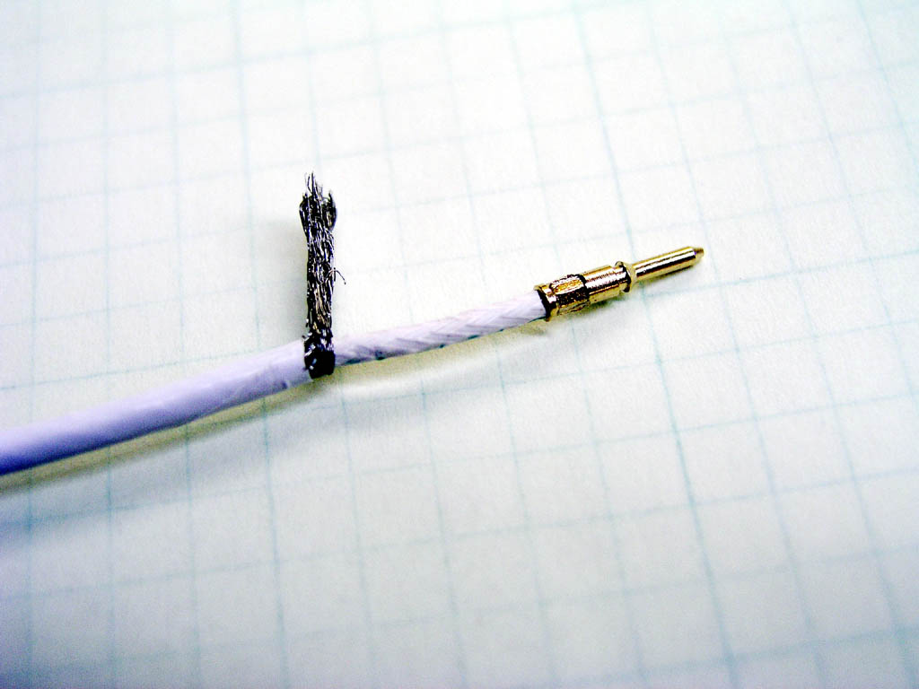
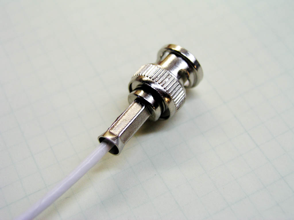
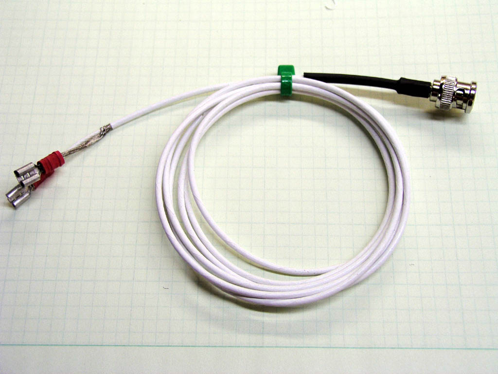
Step 6Since this connector was NOT designed for use with undersized, fake-coax it's a good idea to support the installed connector wire-up and drip 5-minute epoxy into the back. Put a drop in place and "stir" it down by wiggling the wire. When the epoxy has completely enveloped the circumference of the wire, you can suck on the connector to pull epoxy inside. Keep adding drops of epoxy and combinations of wiggle-and-suck until you are assured of center conductor retention. It's not necessary to totally fill the void with epoxy. We're only making sure that a tug on the wire doesn't jerk the center conductor out of its proper resting place in the connector. |
Step 7 |
|
|
Step 8 |
Step 9 |
|
|
Step 10These cables were EXPECTED to receive damage and if a full set of cables lasted only one job, the convenience and time savings made them good value for the task. However, for wiring Klaus' fine ignition system we'd like to see the wiring go in easy, be well rated to the environment and last a very long time with no maintenance. If it were my airplane, it would be wired as described above . . . |
 Click here to contact Bob at AeroElectric Connection Click here to contact Bob at AeroElectric Connection |