![]()
|
Bob's Shop Notes: |
|
From time to time installations call for small components
like diodes, resistors, etc. to be incorporated into system wiring without
really defining where the component will reside. In essence, an "orphaned"
component without a home. While considering the task of providing housing for
a vagrant part, think ROBUST. Not only does the component need to be wired
(the easy part) it should also be protected from mechanical damage due to
normal environmental stresses and maintenance handling. Small diodes in the 1 to 3 amp class are designed to be soldered into an electronic assembly of like components. Little pieces of glass or plastic with solid wire leads can comfortably live in the airframe environment when part of a suitably robust "house". How does one go about housing the occasional "homeless" component? In discussions about joining wires to things we've identified two goals: (1) electrical integrity - gas tight and (2) mechanical integrity - make sure that vibration and normal handling do not attack the natural stress risers that occur in virtually every joining technique. Here are a few suggestions for incorporating some of the occasional orphaned component into your project's electrical system:
|
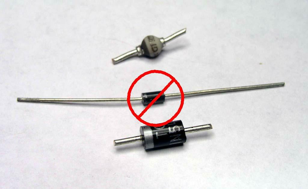
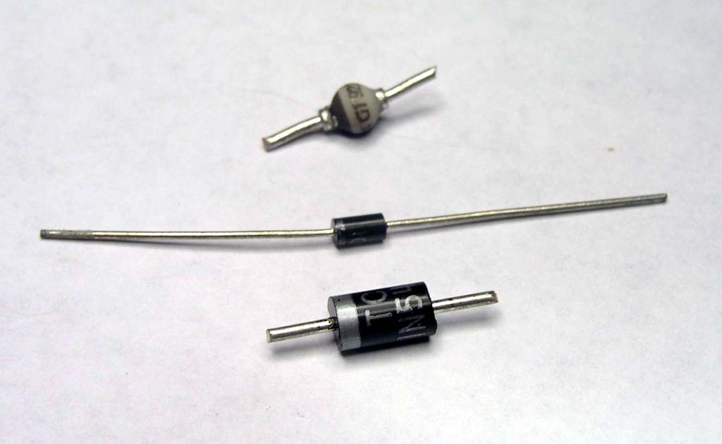
Method 1: Single Components . . .Should the parts list specify a diode as small as 1A, consider substituting a 3A device. The two sizes are illustrated here. Click here for larger image. The 3A devices (1N5400 series devices sold by Radio Shack and others) have larger, 20AWG leads, are mechanically more robust and easier to work with. The larger diode will perform quite nicely in place of the smaller 1A device. Further, ANY diode with a voltage rating of 50V or more is suited for use situations were in-bundle diodes are called for. Trim both leads to about 1/4" as shown here. |
|
|
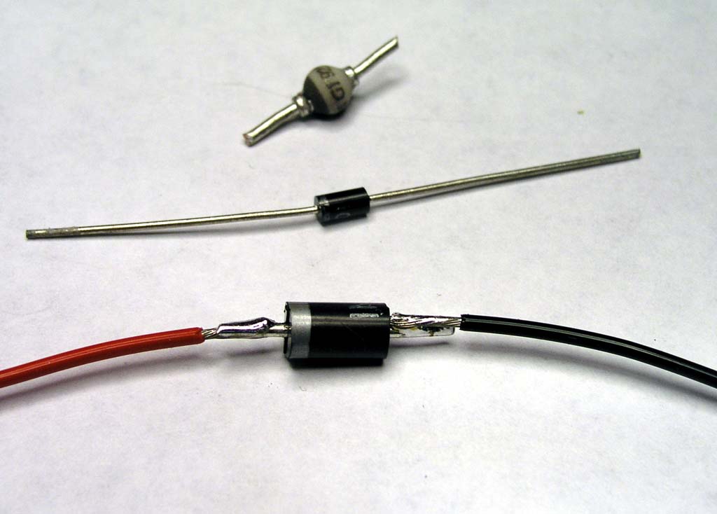
Fabricate pigtails of what ever length is useful. 20AWG is preferred but 22AWG is okay if that
fits your needs better for terminating the other ends. I used red and black here
but any color (or all white) is fine too. You just need to remember which wire is
attached to which end of the diode. Generously "tin" the diode leads and striped ends of the wires. Then "lap" solder the wires to the stub leads on the diode. Click here for larger image.
|
|
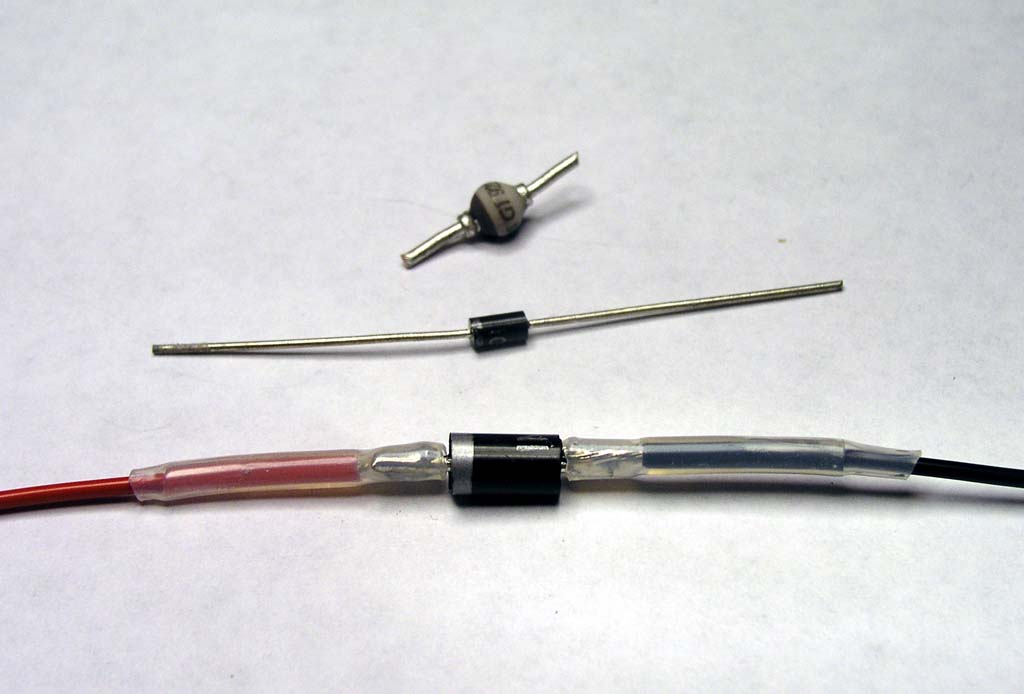
Taking a cue from other wire joining discussions, we know where
the first "soft spot" is for this joint. Whether you crimp or solder stranded wires,
there is value in adding support across the transition area between loose strands
and solidly captured strands. Two layers of heat shrink will manage this task
nicely. Click here for larger image.
|
|
|
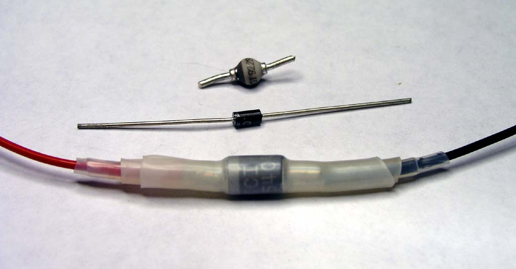
Let's now
consider the OTHER location vulnerable to bending fatigue: The point where the
20AWG solid copper wire emerges from the diode housing. Two more layers of
heat shrink over the whole assembly stiffens this area of the assembly.
Click here for larger image. There you have it. A diode originally intended to occupy a sheltered space within some assembly is ready to assume a long-term assignment within the wild and woolly environment of your airplane's wire bundles.
|
Method 2: Small |
|
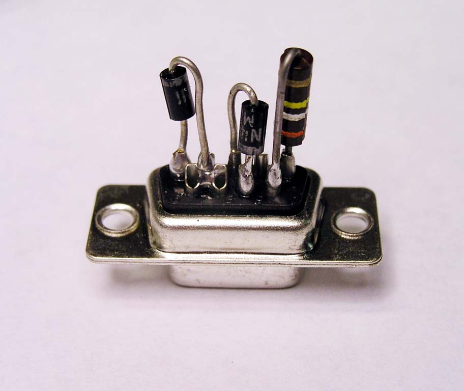
|
Here we see how the D-sub connector back-shell offers compact, inexpensive,
but rugged housing for these small parts. Click here for larger image.
|
|
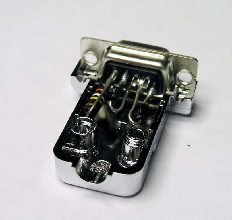
Here I've illustrated a mating connector that brings ship's wiring up to
the finished assembly. You may tie this pair of mated connectors into a wire
bundle -OR- consider bonding a mounting plate to the side of the component
enclosure as seen here. E6000 is an excellent adhesive for this application.
Click here for larger image. You may consider the standard, 4-40 threaded hardware for keeping the connectors mated . . . I prefer the tie-wraps as shown here. Easy to install, easy to replace, won't vibrate loose.
|

|
|
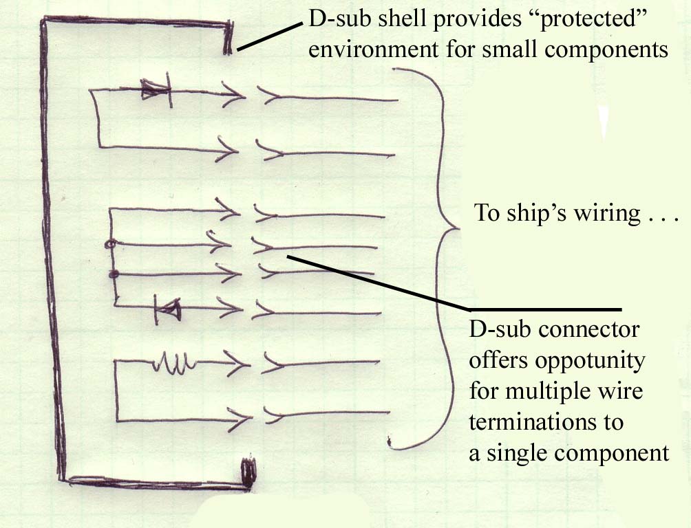
Here's
a schematic for the component assembly cited above. Keep in mind that D-sub connectors
are readily available in 9, 15, 25, and 37-pin sizes. Their back-shells offer handy
volume for housing components that may not fair well if simply tied into
open wire bundles. Click here for larger image.
|
Method 3: The Ultimate in |
|
|
These are but a few suggestions the OBAM aircraft builder may
consider when deciding how to achieve desired electrical functionality
while maintaining a level of robustness that can be expected to endure trouble
free for the lifetime of the airplane. It anyone has more packaging schemes to offer for housing the occasional orphaned component, I'd be pleased to add them to this document. Bob . . . |
 Click here to contact Bob at AeroElectric Connection Click here to contact Bob at AeroElectric Connection |