|
|
Bob's Shop Notes: |
What's all this "BALUN" Stuff Anyhow?The balanced to unbalanced transformation can take on many forms. Further, BALUNS are used at all points in the frequency spectrum from audio system to GigaHertz radios. There are many articles and descriptions of BALUNS on the 'net. For the interested individuals, I'll offer this one on Wikipedia and this one from the Amateur Radio Relay League. From our perspective as airplane builders, we have an interest in two separate but loosely related features of an antenna system. One is the efficient transfer of power between the antenna and the feedline that conducts power to or from the ship's radios. There's a figure of merit in antenna systems called "loss or gain". Feedlines ALWAYS lose a little energy by allowing it to be converter to heat (resistive loses) or go astray (standing wave ratio). Antennas can also be said to have "gain" when and if they take the radio energy of interest and CONCENTRATE on one direction for either listening or receiving. This gain or loss of energy based on direction is a function of the antenna's second figure of merit, the radiation/reception pattern. This is discussed in the ARRL article cited above.
|
|
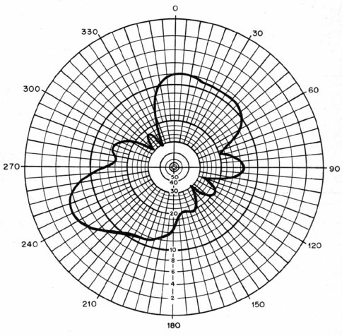
Click here for larger image. The BALUN being discussed in the comic book below is intended to augment the performance of an aviation Visual Omni Range (VOR) antenna. The "ideal" VOR antenna would be a dipole in free space having a radiation pattern like that shown in Figure 1 of the ARRL article. We'd like to orient the antenna so that major lobes for sensitivity are oriented fore and aft along the aircraft centerline. However, when we mount the "perfect dipole" on the airplane and attach a coaxial feedline to it, ugly things can happen that cripple the antenna's ability to perform perfectly. This is illustrated in Figure 3 of the ARRL article and repeated here. Distortions of the perfect radiation pattern are a combination of TWO things . . . feedline compatibility and proximity of parts of the airplane. We can't do much about the second effect but installing a BALUN will help for the first. Pretty funky radiation pattern, no? Before you run off and rip out your VOR antenna installation to add a BALUN, is your antenna performing okay now? And when you perceived that it MIGHT need some help, are you sure that the deficiency in operation was not related to something besides a distorted radiation pattern? The way to tell is when you're trying to hear a station that is a considerable distance away, fly a relatively flat 4 minute turn and see if the station's audibility goes through some profound changes. If so, your system might benefit from the addition of a BALUN. Keep in mind that our radios are talking/listening to stations we can essentially "see", i.e. line of sight. There are tens of thousands of VOR antennas flying without benefit of a BALUN where what ever pattern distortions caused by the feedline are not bad enough to cause heartburn. |
|
| If you have yet to install your VOR antenna or you're replacing a damaged one, the adding a BALUN to the installation can be considered. Check over the data offered below. While it's probably not necessary that your VOR antenna system have a BALUN, it's not difficult to do. Further, it's an activity that exploits "the-best-we-know-how-to-do". |
|
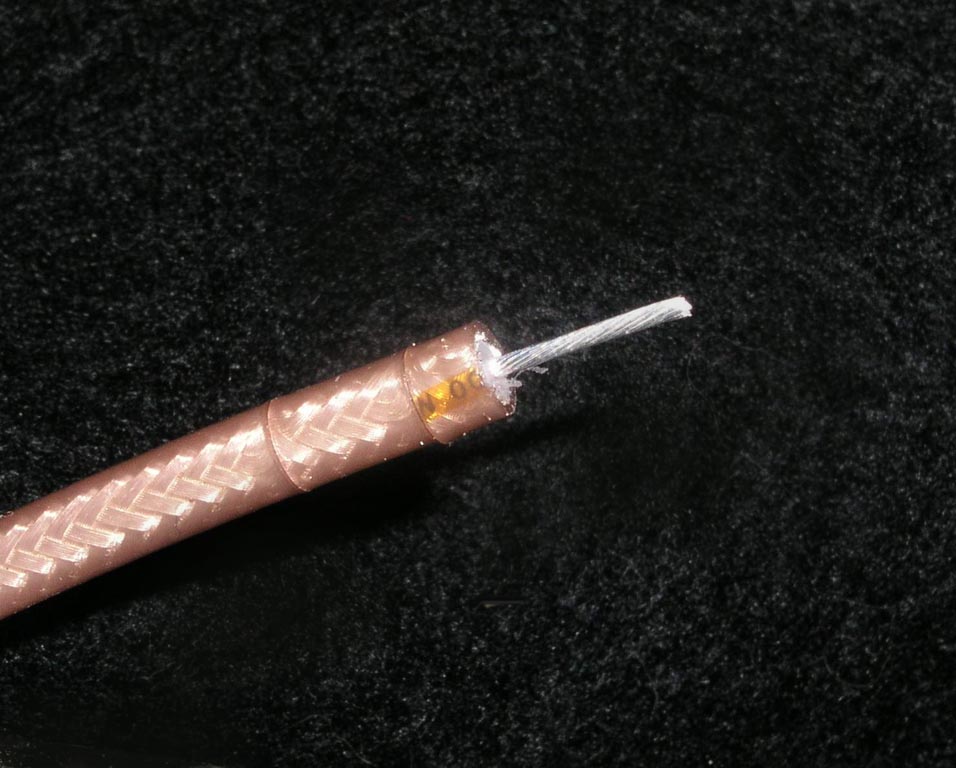
Step 1 . . .Strip your Nav receiver feedline as if you were going to install a BNC connector. There are a number of handy tools to make the correct cuts that you can see in this photo. It wouldn't hurt to set the tool back for about 3/4" of exposed center conductor. I only cut it about 1/2" in this view. |
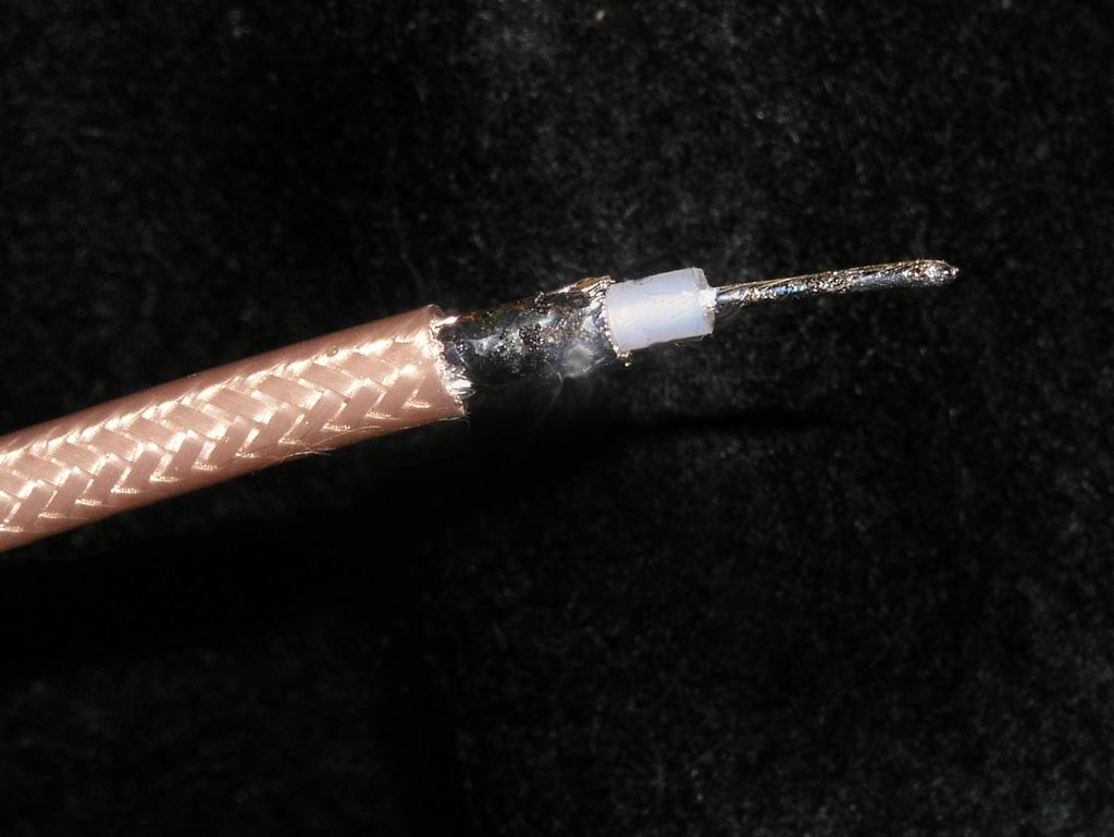
Step 2 . . ."Tin" the exposed center conductor and braid with solder . . . |
|
|
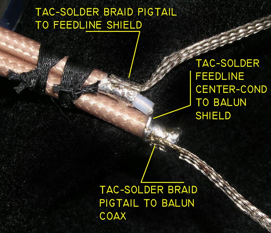
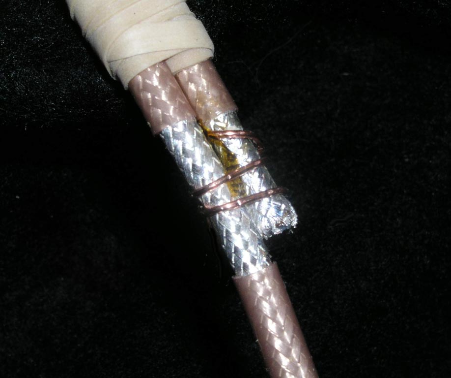
Step 3 . . .Cut a second piece of "balun" coax 27" long and expose 1/2" of braid at each end. I've modified a coax stripping tool by removing all but the outer jacket knife. "Tin" the exposed shield braid. Firmly fixture the balun coax against the feedline coax as shown here. I used a couple of 4-pass string ties here. Cut some 3" pieces of single conductor shielded wire. Pull the center conductor out followed by the shield to acquire some short pieces of braided wire for "pigtails". Wrap the feedline center conductor around the balun shield and solder. Tac-Solder the pigtails to the coax shields as shown here. |
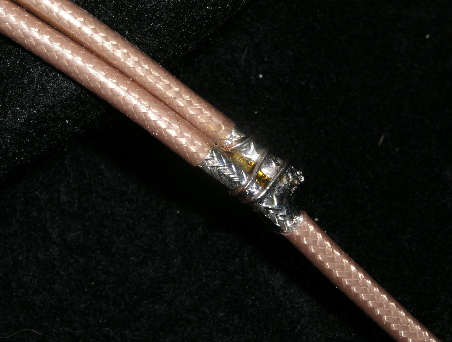
Step 4 . . .Here I used the special one-knife coax stripper to remove a section of feedline outer jacket immediately adjacent to the other end of the balun coax. I've used a scrap of 22AWG solid wire to fixture the two exposed braids against each other. Any handy wire will do. You can cut a 2-3" chunk of heavier wire like 14 or 12AWG and salvage a couple of strands of wire out of the layup. Any small wire that will solder readily into the finished joint is fine. |
|
|
Step 5 . . .Here's the place where the venerable ol' RG-58 falls off the horse. You need to solder this joint and the materials from which RG-58 is made just will not stand up to the heat. |
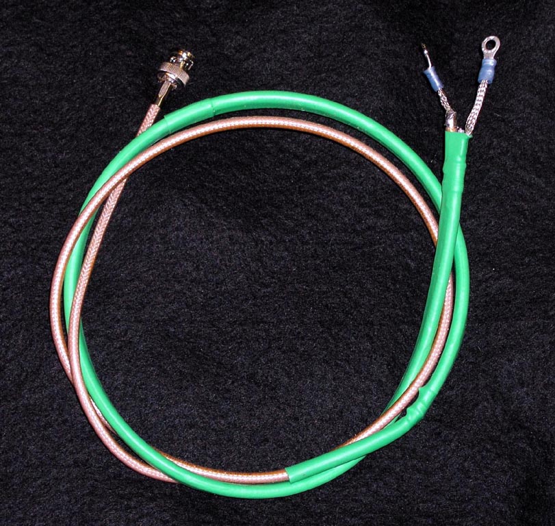
Step 6 . . .Cover the finished balun with heat shrink. Make sure you don't cut your pigtails off too short before you install terminals compatible with the ends of your VOR antenna rods. Understand that this BALUN puts a DC dead short across the end of your receiver's feedline coax so don't be alarmed if you put the ohmmeter or continuity tester to this piece of coax and it tests "shorted".
|
|
|
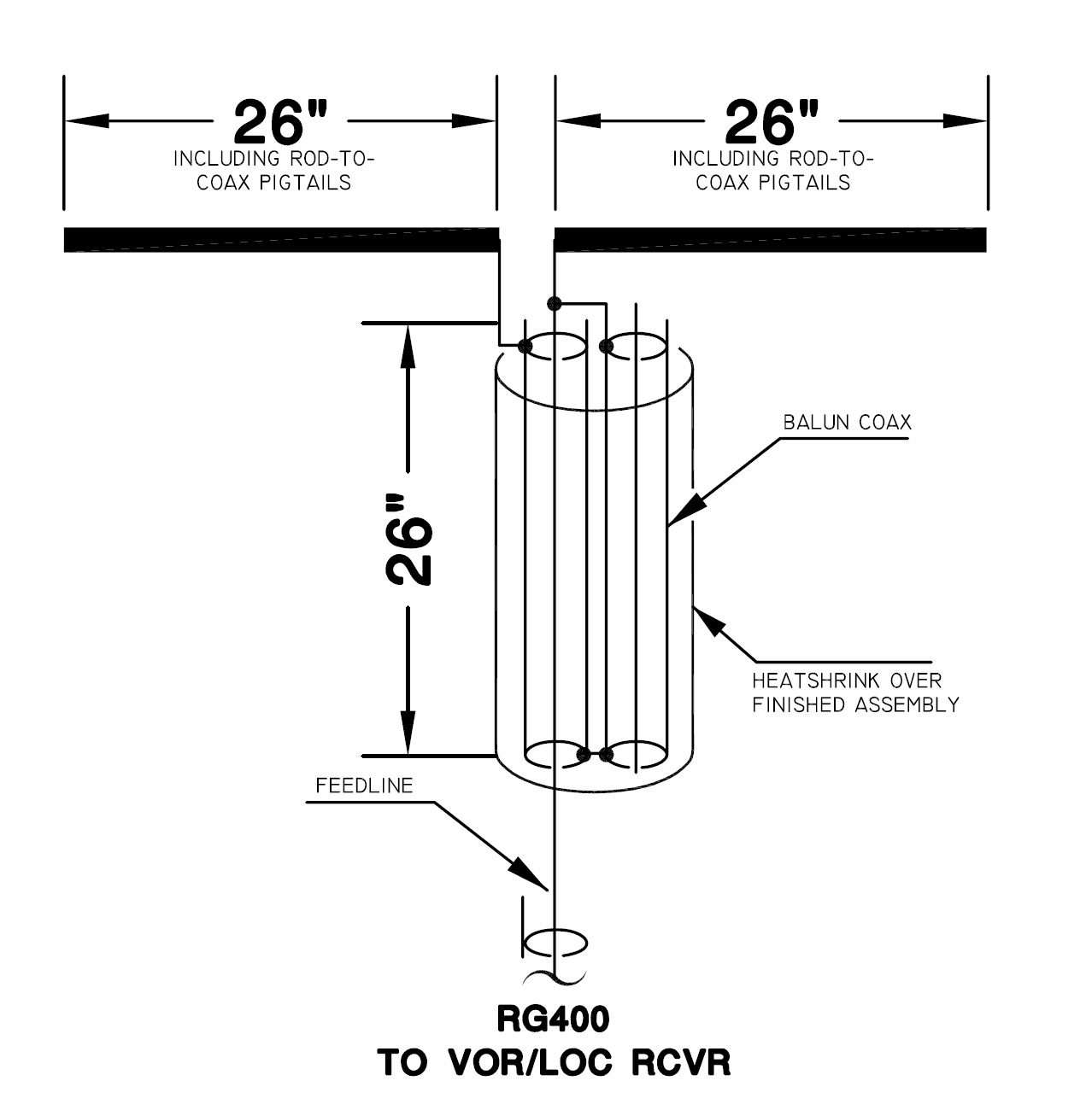
Yer Done! . . .Here's a schematic diagram for the BALUN described above . . . |